What is the real-world maximum range and throughput integrators can trust from PtMP?
What is the real-world maximum range and throughput integrators can trust from PtMP?
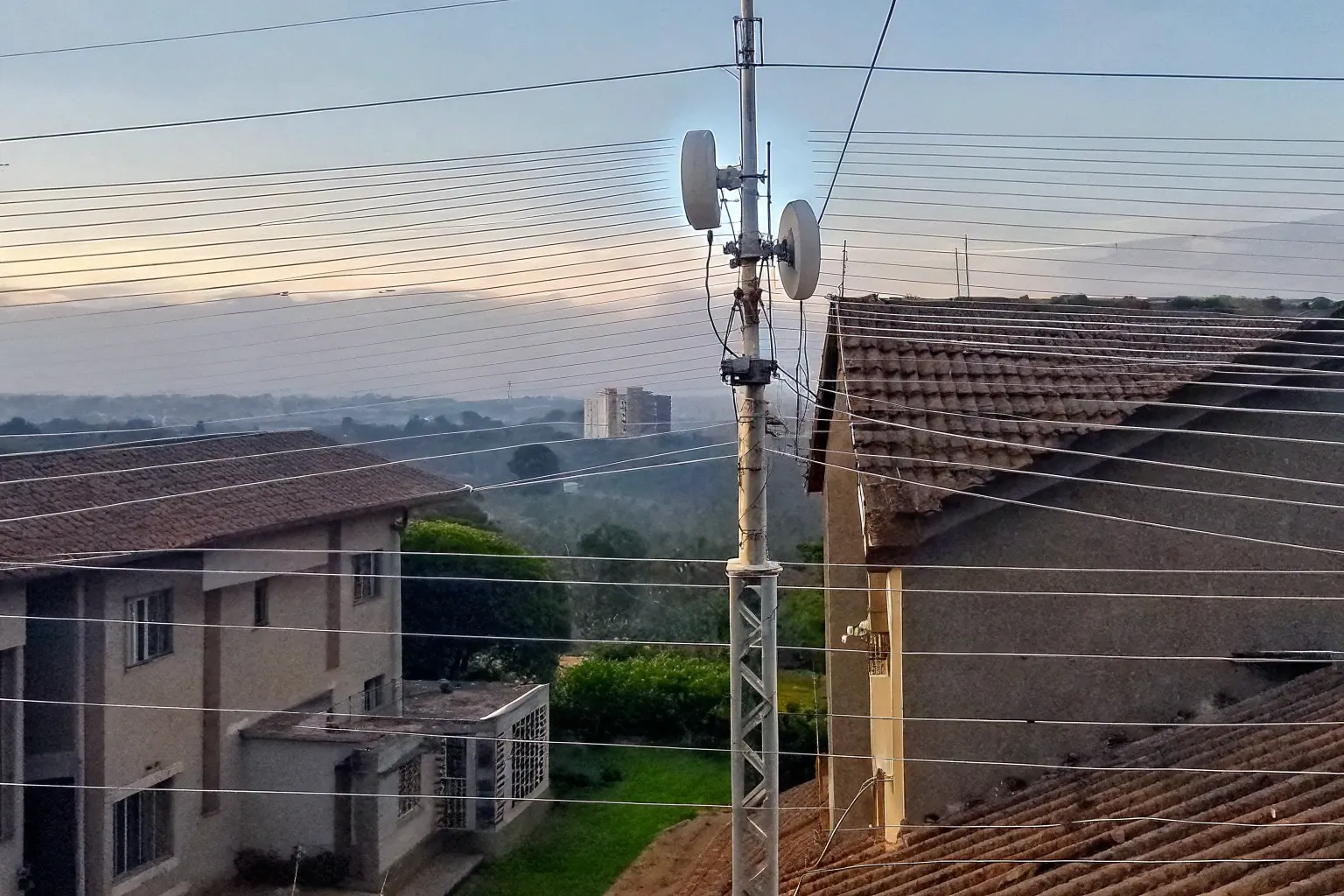
When we buy new Wireless Bridges for our **WISP** projects, we see huge “up to” numbers on the datasheet. But honestly, those theoretical maximums almost never match what we see in the field. This gap between promise and reality hurts our project budgets and causes expensive truck rolls. We need performance we can actually deliver to our customers.
Real-world **PtMP Deployment** range and throughput are strongly dependent on noise, distance, and subscriber density, not just datasheet peaks. In practice, most system integrators achieve a reliable aggregate throughput of **100–500 Mbps** per sector when serving clients between **5 and 20 kilometers** under good Line-of-Sight conditions. We have found that stability is often traded for raw speed, especially on long links.
We all want guaranteed performance before we commit to bulk orders. We must shift our focus from “maximum” ratings to **real-world baselines**. Let us break down the engineering principles that truly govern the performance of your next **CCTV Backhaul** or rural broadband project. This is the difference between a successful contract and constant frustration.
How do I estimate my actual PtMP performance based on my installation environment?
Many of us focus only on the distance rating on the box. That “max range” only tells us if the signal *might* get there. It does not tell us if the link will actually *work* well. We need a better method to predict reliable speed before we even climb the tower.
You must estimate performance using a rigorous **Link Budget Analysis** that incorporates the **Fresnel Zone clearance** and the local noise floor, not just the vendor’s maximum distance claim. Reliable **PtMP Deployment** performance requires a received signal level ($\boldsymbol{R}_{\boldsymbol{x}}$) stronger than **-70 dBm**, which often limits real-world range to **20 miles (32 km)** or less, depending on antenna size.
Understanding the Link Budget: The True Performance Predictor
We need to treat the wireless link like any other engineered system. The **Link Budget** is the mathematical tool that tells us exactly what signal strength the receiver will see. If we do not hit a minimum received signal strength, the link modulation rate (MCS) will drop, killing your throughput. We have seen many new **System Integrators** make this mistake by only relying on visual line-of-sight.
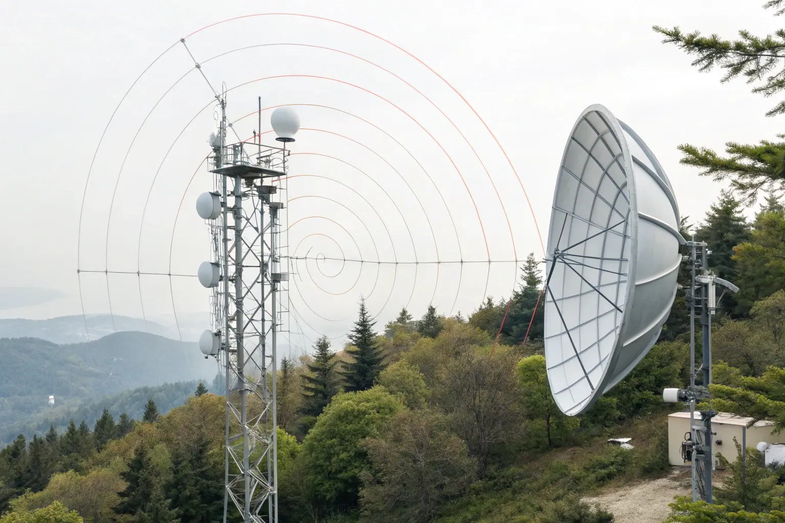
The Link Budget calculation considers the radio’s transmit power, the gain of the antennas (both Sector AP and the CPE), and the losses over the air (Free Space Path Loss). Free Space Path Loss is severe. For a 20 km link in the 5 GHz band, the path loss is over 134 dB. This is why we need high-gain antennas, like the 25 dBi+ dishes used on Mosslink Wireless Bridges, to recover that signal. This is non-negotiable for stable performance at the edge.
The Critical Role of the 60% Fresnel Zone
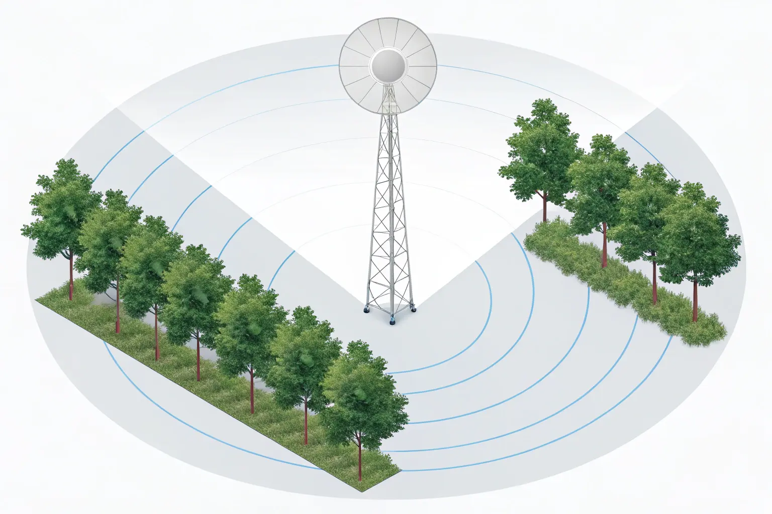
The Earth is not flat, and radio waves do not travel in a straight line. They travel in an ellipsoid shape called the **Fresnel Zone**. We must ensure that at least **60% of this zone is clear** of any obstructions, like trees, ground mounds, or building edges. Obstructions within this zone introduce multipath interference and signal loss, which severely degrade the signal-to-noise ratio (SNR). This degradation directly forces the radio to use a lower, slower modulation code, sacrificing throughput for stability. Ignoring this rule is a guaranteed way to see a **50% throughput drop** in real-world scenarios, even with clear visual LOS. We use this principle on all our **PtMP Deployment** projects.
The Throughput vs. Range Trade-off
The maximum advertised range is usually achieved at the lowest possible data rate (e.g., MCS 0 or 1), which might only give you 5–10 Mbps of usable throughput. This is useless for high-demand residential or **CCTV Backhaul** services. As a practical rule, to maintain high throughput (MCS 7+), we must keep the received signal strength strong, often limiting the maximum range to about **15–20 km** for high-density deployments. For example, a **WISP** targeting 50 Mbps per subscriber must keep them closer than one targeting 5 Mbps. This is the difference between a theoretical range and a useful range.
According to field reports and demos, even powerful modern systems show significant degradation. A Cambium demo with a 40 MHz channel at 23–24 km reported around 230–250 Mbps TCP/UDP throughput, demonstrating what is possible at long range but confirming the significant loss compared to the gigabit PHY rates. We always advise setting expectations based on achievable $\boldsymbol{R}_{\boldsymbol{x}}$ levels, not theoretical miles. This practical data helps **System Integrators** quote reliable services to their end clients. You can see how real-world performance looks when pushed to the limit in this WISP Demo on Long Range Performance (YouTube).
| Real-World Link Type | Distance Baseline (Typical Max) | Required $\boldsymbol{R}_{\boldsymbol{x}}$ (Signal Strength) | Expected Aggregate Throughput (40MHz Channel) |
|---|---|---|---|
| Short-Haul CCTV/Campus PtMP | 0.5 – 5 km | -50 to -60 dBm | **350 – 500 Mbps** |
| Mid-Range WISP Rural PtMP | 5 – 15 km | -60 to -68 dBm | **200 – 350 Mbps** |
| Long-Range WISP Edge PtMP | 15 – 32 km (20 miles) | -68 to -72 dBm | **100 – 200 Mbps** (Stability Focused) |
We focus our **Mosslink** bridge designs on having high transmit power and superior receiver sensitivity. We engineer for the target $\boldsymbol{R}_{\boldsymbol{x}}$ level needed for high MCS rates, not just for the distance. If you want high speed, you must prioritize signal quality over distance every time. This insight comes from working with **System Integrators** who repeatedly see poor performance when they push the distance limit too hard. Our goal is to provide **Wireless Bridges** that deliver the promised speed at the quoted range.
What factors will limit my real-world PtMP range and throughput the most?
When we install our equipment, the biggest enemy is always the one we cannot see. It is not the distance itself that kills the link, but the **invisible noise** that forces our radios to slow down. Without addressing noise, you will never reach maximum range or throughput.
The three greatest limits on real-world **PtMP Throughput** are **RF Interference**, the overall **Client Density** on the sector, and the choice of air interface protocol. **RF Interference** in the crowded 5 GHz band is the silent killer, often forcing modulation levels to drop and increasing packet retransmissions, which drastically reduces the available throughput per subscriber.
RF Interference: The Invisible Throughput Killer
Let us be clear: **RF Interference** is the number one cause of poor performance. It does not often cause a full link failure, but it constantly introduces errors. When the radio detects an error, it must retransmit the data, or it must drop its modulation coding scheme (MCS) to a lower, more robust setting. Both actions reduce usable throughput. We have seen cases where the noise floor is so high that the usable capacity of a 40 MHz channel drops from 400 Mbps to under **100 Mbps**. This situation destroys profitability for **WISPs**.
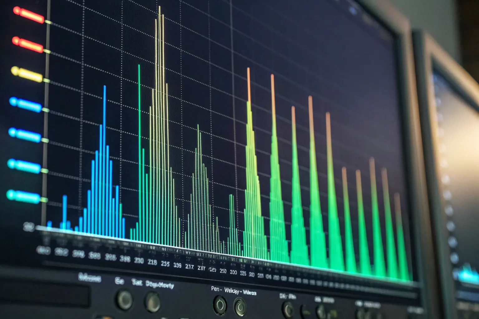
In the highly congested 5 GHz frequency band, interference comes from many sources: competing **WISP** towers, high-power neighboring **Wireless Bridges**, and even high-end business Wi-Fi Access Points. The solution is not always more power; it is better selectivity. Our Mosslink sector antennas use high front-to-back ratios and tight beamwidths to minimize picking up noise from unwanted directions. We strongly advise **System Integrators** to use a built-in spectrum analyzer before activation to find the cleanest slice of the band. You can read about the impact of this noise on other operator deployments in this WISP Reddit Discussion on Real-World Speeds.
Protocol Overhead: Total Sector vs. Usable User Throughput
The promised headline throughput (e.g., 1.7 Gbps) is the **Total Sector Throughput**. This is a theoretical PHY rate. You do not get to use all of it. Why? Because the wireless medium is shared. Every user’s data, plus overhead from the protocol (ACKs, encryption, frame headers), consumes “airtime.” In a standard 802.11 (Wi-Fi) PtMP system, collisions and retransmissions waste a significant amount of airtime.
This is where protocols like **TDMA (Time Division Multiple Access)** become essential. Standard 802.11 allows radios to talk whenever they hear a clear channel. **TDMA** assigns specific time slots for each CPE to talk to the AP. It eliminates collisions, increases efficiency, and ensures that even remote clients get a fair share of airtime. **This is why we designed our Mosslink PtMP radios with a private TDMA protocol.** It is specifically optimized to maintain stable throughput for high-demand services like **CCTV Backhaul**, where consistent bandwidth is more critical than peak speed. Without optimized **TDMA**, you should only expect about **40–60%** of the advertised PHY rate as actual TCP/UDP throughput.
The Challenge of Client Density and Oversubscription
Because the throughput is shared, every active client eats into the total sector capacity. This is a hard limit on real-world performance. In PtMP, performance is not determined by the distance of the furthest client, but by the **highest number of active clients** demanding service simultaneously. For modern systems, a reliable upper bound for a clean, loaded sector is around **500 Mbps** aggregate downlink, even with advanced MU-MIMO technology. This is evident in real-world scenarios, such as the Cambium Networks Case Study on MU-MIMO throughput which demonstrated strong results with 53 subscribers.
For mission-critical **CCTV Backhaul** systems, oversubscription is a high-risk strategy. We always recommend budgeting **at least 5 Mbps guaranteed** for every 4K camera and designing the sector to handle the full aggregate load. This prevents video loss during peak security events. For **WISPs** serving residential customers, the goal is often a reliable 20–30 Mbps per subscriber. This requires careful capacity planning and knowledge of user consumption patterns, as discussed by experts in this Meter.com Resource on PtMP.
| Factor Limiting Throughput | Impact on Performance | Solution with Mosslink Products |
|---|---|---|
| RF Interference (5 GHz Noise) | Forces lower MCS rates, high packet retransmission. | High Front-to-Back Ratio Antennas, Built-in Spectrum Analyzer, and Private **TDMA**. |
| Client Density & Airtime | Each additional client reduces available time slots for others. | Private **TDMA** Protocol ensures fair, collision-free airtime scheduling for all subscribers. |
| Distance & Signal Fade | Drops received signal ($\boldsymbol{R}_{\boldsymbol{x}}$), forcing links to the slowest modulation. | |
| Distance & Signal Fade | Drops received signal ($\boldsymbol{R}_{\boldsymbol{x}}$), forcing links to the slowest modulation. | High-Gain CPEs (e.g., 27 dBi) and High-Tx Power **Wireless Bridges**. |
We need robust equipment that can fight back against these invisible limits. Our private TDMA protocol and high-quality radio components are built specifically to maintain high SNR in noisy conditions. This gives our **System Integrators** the confidence to deploy in complex environments, knowing the throughput will hold up when needed most.
How can I optimize my PtMP setup to improve my real-world speeds?
We often hear from clients who have great line-of-sight but still see poor speeds. Usually, the problem is not the hardware itself; it is the **configuration and power management**. We can dramatically improve performance with a few key field-tested steps.
You can improve real-world speeds by performing meticulous **Antenna Alignment**, carefully selecting the narrowest possible **Channel Width** to minimize noise, and integrating smart power management tools like the **PoE Watchdog** feature found in our Mosslink Managed PoE Switches. Optimizing these three areas provides the cleanest signal and the most reliable connection for the maximum possible **PtMP Throughput**.
The Channel Width vs. Noise Trade-off
Channel width determines how much data you can transmit, but also how much noise you collect. A wider channel (e.g., 40 MHz) provides high peak throughput, but it also captures twice the background noise of a 20 MHz channel. In high-interference urban areas, a narrow channel is often the better choice. We often advise **System Integrators** to run a **20 MHz channel** in congested sectors, even if it halves the peak throughput. Why? Because a stable 200 Mbps is better than an unstable 400 Mbps that keeps dropping to 50 Mbps. This ensures consistent service for all users in your **PtMP Deployment**.
For rural **WISP** areas with very clean spectrum, using a 40 MHz or even 80 MHz channel is an easy way to boost capacity. However, you must always verify the noise floor before selecting a wider channel. Our **Mosslink** radios allow granular control over channel widths (5/10/20/40/80 MHz), giving you the flexibility to adapt to any environment and ensure stable **PtMP Throughput**.
Antenna Alignment: The Single Most Important Step
A one-degree error in antenna alignment can degrade the signal by 3–5 dBm. This small drop can be the difference between using a high MCS rate (high speed) and a low MCS rate (low speed). We have seen it hundreds of times. Professional **System Integrators** use the radio’s built-in alignment tools to fine-tune the link until the $\boldsymbol{R}_{\boldsymbol{x}}$ number is maximized and balanced across both polarities (H/V). For long-distance Wireless Bridges, the difference between -65 dBm and -60 dBm is massive in terms of available capacity. Every dBm of signal strength gained through alignment translates directly into higher modulation and increased speed.
| Channel Width | Peak PHY Rate (Example) | Noise Captured | Best Use Case |
|---|---|---|---|
| **10 MHz** | 80 Mbps | Low | Extreme range or highly congested environments. Stability first. |
| **20 MHz** | 160 Mbps | Medium | Standard rural **WISP** and reliable **CCTV Backhaul**. Good balance. |
| **40 MHz** | 320 Mbps | High | Clean spectrum areas for high-density residential PtMP. Maximum speed. |
Smart Power Management: The PoE Watchdog Advantage
While this is technically not an RF factor, it is a critical optimization for uptime. In a **CCTV Backhaul** network, IP cameras sometimes freeze or lose communication due to minor power fluctuations or software glitches. Without a **PoE Watchdog**, an installer must drive to the site and manually power-cycle the camera. This costs time and money. This is the hidden cost of unreliable networks.
Our **Mosslink Managed PoE Switches** include a smart **PoE Watchdog** feature. The switch constantly pings the IP address of the connected camera or Wireless Bridges. If the device stops responding, the switch automatically cuts power to that specific port for a few seconds and then restores it, forcing a reboot. This simple feature drastically reduces truck rolls and ensures maximum uptime for the client. For any **System Integrators** focused on cost efficiency, the PoE Watchdog is an essential tool. We recommend using a **Mosslink 802.3at/bt PoE Switch** to ensure enough power for all remote devices. We also advise stocking up on Mosslink Hi-PoE Switches to support high-power WiFi 6 APs and PTZ cameras.
How do I choose the right PtMP radios to meet my project’s real-world performance needs?
When we buy network gear, we are not just buying a radio; we are buying guaranteed service delivery. Choosing the right radio means looking past the giant MPH numbers and focusing on three core dimensions: **Coverage, Capacity, and Stability**. If you choose based on price alone, your performance will suffer.
Choosing the right PtMP radio means prioritizing a proprietary **TDMA** protocol over standard 802.11 for better airtime efficiency, verifying **Antenna Gain** (dBi) to ensure link budget closing, and confirming **PoE Standards** (802.3at/bt) for reliable power delivery to remote CPEs. For real-world success in **PtMP Deployment**, we must always combine high-performance Wireless Bridges with intelligent power from quality **Mosslink Managed PoE Switches**.
The Three Dimensions of PtMP Selection
Effective PtMP selection balances three factors: **Coverage (Range)**, **Capacity (Throughput)**, and **Stability (Uptime)**. We cannot maximize all three at once. A **WISP** aiming for maximum **Coverage** (30 km+) must sacrifice **Capacity** to ensure **Stability**. A **CCTV Backhaul** project prioritizing **Capacity** (high bandwidth for 4K video) must usually limit **Coverage** (keep links short). You must define your primary goal first.
When selecting the CPEs (Client Premises Equipment), pay attention to the advertised **Antenna Gain**. A higher gain (e.g., 27 dBi) CPE can “hear” the sector AP better and transmit back more efficiently, which is critical for closing the link budget on long shots. We at **Mosslink** always pair our high-power sector radios with our specialized high-gain CPEs to ensure the best possible signal return path, even for challenging **PtMP Deployment** locations. The physical radio design and engineering must match your deployment needs.
Choosing the Right Protocol: TDMA vs. Standard WiFi
While the newest generation of gear uses **WiFi 6 (802.11ax)** modulation, the real key to PtMP success is the **TDMA** layer built on top of it. **WiFi 6** gives us better spectral efficiency and Multi-User MIMO (MU-MIMO), meaning the AP can talk to multiple CPEs simultaneously. This is a game-changer for **PtMP Throughput**.
However, if the CPE is too far away or has a poor signal, it will not be able to take advantage of the high-speed MU-MIMO/WiFi 6 modes. In these cases, the proprietary **TDMA** scheduling protocol will keep the link stable, even if the speed is lower. We have found that the stability offered by our private TDMA protocol provides more reliable overall performance than a system that relies purely on the standard 802.11ax feature set. **System Integrators** must always choose a system where the vendor controls and optimizes the air-interface protocol layer. You can find more authoritative data on the real-world performance differences and throughput losses experienced by operators using older protocols in this academic paper: Real-World Throughput of Wireless Networks (Wiley).
| Feature Metric | Legacy PtMP (WiFi 5/802.11ac) | Modern PtMP (WiFi 6/TDMA) | Mosslink Advantage |
|---|---|---|---|
| Throughput per Sector | 250 – 500 Mbps Aggregate | **500 – 1000 Mbps Aggregate** | High total capacity for high-density **WISP** and enterprise use. |
| Protocol Efficiency | Prone to collisions, variable latency | Uses **TDMA** / Polling; fixed, low latency | Guaranteed airtime for every client, essential for stable **CCTV Backhaul**. |
| Latency | 10 – 40 ms | **3 – 10 ms** | Excellent for VoIP and remote desktop applications. |
| Max Client Capacity | Typically 40–60 clients per sector | **80+ clients per sector** | Allows **System Integrators** to scale their network more aggressively. |
The Power Requirement: Don’t Starve Your CPEs
Finally, we circle back to power. Modern high-power CPEs and Wireless Bridges (especially those with gigabit radios and high-gain internal amplifiers) require more power than standard 802.3af (PoE) can deliver. They often require the higher wattage provided by **802.3at (PoE+)** or even **802.3bt (Hi-PoE)**, which can supply up to 90W. Using an underpowered PoE switch will lead to unstable operation, especially during cold weather when internal heating elements may draw extra power. This is the mistake that costs **System Integrators** the most in labor.
When you stock your inventory, ensure your **PoE Switches** are clearly labeled with their total power budget and per-port standard. Our Mosslink Managed PoE Switches are designed with generous power budgets to support a full sector of high-power CPEs, eliminating the risk of device starvation and the resulting performance drops. We also offer advanced Mosslink Router solutions that simplify the central management of both power and network traffic. You can find more detail on this topic in this Alshareef Security article on PTP to PtMP Switching.
Mosslink Engineering Recommendations
We know you are building mission-critical networks where instability is not an option. Focus on optimizing the signal quality and power delivery, not just raw distance. The true performance of your **PtMP Deployment** rests on rigorous Link Budget planning, proactive noise mitigation, and intelligent power management using the **PoE Watchdog** feature. We are here to partner with you, providing the stable Wireless Bridges and intelligent **PoE Switches** your large projects demand.
— Contact Our Global Sales Team —
We provide specialized technical support and volume pricing for **System Integrators** and **WISPs** worldwide. Reach out to discuss specifications for your next high-capacity **CCTV Backhaul** project.
Share